
Safety Equipment
-
Vehicle Restraint
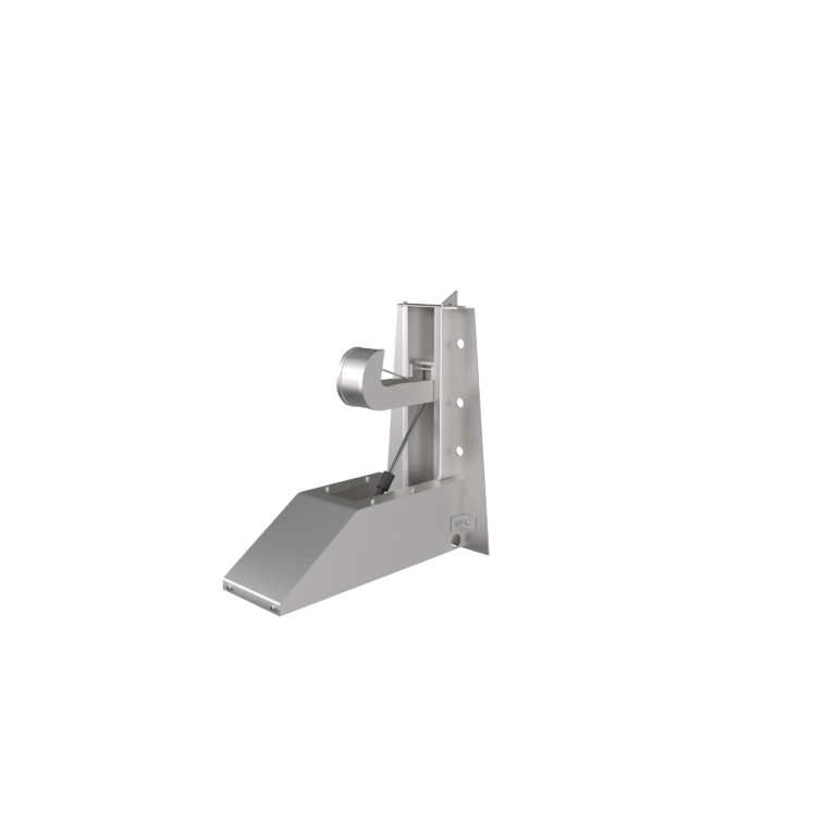
Definition & Core Function Vehicle Restraint is a safety device used in logistics loading and unloading operations to secure trucks to the dock leveler. It mechanically engages with the truck's rear impact guard or designated anchor point, preventing unintended vehicle movement (such as rolling or premature departure) during loading and unloading. This reduces the risk of personal injury and cargo damage. Its core function is to establish a rigid connection between the truck and the dock leveler, making it a critical component of modern logistics safety systems. Working Principle Once the truck is docked, the operator activates the restraint hook by rotating a handle. At this point, the dock leveler and truck are securely locked together, allowing safe loading operations. After unloading is completed, the operator rotates the handle again to retract the hook, releasing the vehicle so it can depart. Electric (Intelligent) Vehicle Restraint: Equipped with motor drive and PLC control system. Supports remote operation and IoT monitoring (e.g., checking lock status via mobile app). Designed for automated logistics centers. Vehicle Restraint Parameters Parameter Typical Value Function / Purpose Clamping Force 50–100kN Ensures the truck is securely restrained and resists accidental forces. Compatible Rear Impact Guard Height 300–600mm (adjustable) Accommodates different truck rear structures. Response Time ≤ 2 seconds (from activation to lock) Improves operational efficiency and reduces waiting time. Safety Certification CE (European Union) Complies with international safety standards, ensuring reliable use. Application Scenarios & Installation Guidelines Typical Scenarios: Logistics Warehouse Docks: Used in combination with dock levelers and dock seals to form an integrated "Vehicle Restraint – Sealing – Loading/Unloading" safety workflow. For example, every dock at Amazon logistics centers is equipped with a vehicle restraint as standard. Cold Chain Warehousing: Vehicle restraints are installed at cold storage docks to prevent truck movement and potential cold air loss, even under low-temperature conditions where mechanical malfunctions may occur. Hazardous Materials Handling Areas: Stainless steel restraints with anti-static design are used for loading and unloading chemical materials, fuels, or other hazardous goods, eliminating spark risks. Installation Guidelines: Position Calibration: The center of the vehicle restraint must align with the truck's rear impact guard with a horizontal deviation of <50 mm and vertical deviation ≤30 mm to ensure precise engagement. Foundation Reinforcement: The mounting base must be cast with C30 concrete (thickness ≥300 mm), and embedded anchor bolts should have a tensile strength of ≥Grade 10.9. Interlock Design: Integrate with dock levelers and high-speed doors to form an interlocking logic (e.g., doors cannot open unless the vehicle is properly restrained) to prevent operational errors. Integration with Other Safety Devices Device Integration Method Safety Value Truck Positioning Lights Guide trucks to accurately stop within the operating range of the vehicle restraint. Reduces engagement errors and improves locking success rate. Audible & Visual Alarms Emit warning signals during locking/release operations. Alerts nearby personnel, preventing accidental entry into hazardous areas. Dock Edge Guardrails Prevent personnel from falling and work together with the vehicle restraint to form a three-dimensional safety barrier. Reduces overall safety risks during loading and unloading operations. Surface Treatment: The vehicle restraint hook is treated with cold galvanization or electrostatic powder coating.
View Details -
Sponge Dock Seal
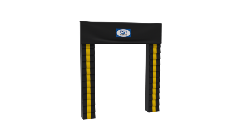
Definition & Core Function Sponge Dock Seal is a sealing accessory made primarily of sponge material, installed along the edges of doors or door frames. It fills gaps through elastic compression to achieve: Soundproofing, Dustproof & Waterproof: Blocks external noise, dust, and rain from entering indoor spaces. Thermal Insulation: Reduces air exchange between indoors and outdoors, helping to save energy for air conditioning or heating. Impact Cushioning: Reduces impact when closing doors, protecting both the door and the frame. Due to its low cost and easy installation, sponge dock seals are widely used in residential buildings, offices, hotels, and light industrial settings. Core Materials & Structure: Sponge Type: PU Sponge (Polyurethane) Advantages: High elasticity, adjustable density, suitable for applications requiring strong sealing (e.g., equipment doors). Disadvantages: Prone to mold when exposed to moisture for long periods, requiring a waterproof coating. Auxiliary Structure: Adhesive Backing Layer: Uses wooden or steel frames for easy and secure installation. Metal/Plastic Slots: Some models require embedding into door frame slots for enhanced durability. Specifications & Airtightness Dimensions WxH Sponge Width Sponge Thickness Curtain Length Air Tightness Sealing Performance 2600x2800 300mm 250mm 900mm 95% 3000x3000 300mm 250mm 900mm 95% 3000x3300 300mm 250mm 900mm 95% Note: Customization for special sizes is available upon inquiry.
View Details -
Mechanical Dock shelter
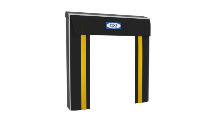
Definition & Core Function Mechanical Dock Shelter is a sealing device driven by mechanical structures or external force, distinct from flexible seals such as sponge or rubber. Its core mechanism relies on rigid components combined with elastic elements (e.g., springs, metal pressure strips) or mechanical locking systems to generate continuous pressure when the door is closed. This ensures: High Airtightness: Blocks air, liquids, dust, and other substances. High Strength & Impact Resistance: Suitable for high-pressure, high-temperature, or heavy-load environments. Precise Sealing Control: Allows accurate adjustment of sealing pressure via mechanical tuning. Mechanical dock seals are widely used in industrial equipment, ships, aerospace, and medical devices, where strict sealing requirements are essential. Working Principle Example For a spring-type mechanical dock seal, when the door closes, the spring is compressed to generate thrust, pushing a metal pressure strip that presses the sealing gasket against the door frame. This creates a dual sealing effect of "Mechanical Force + Elastic Deformation". Specifications & Airtightness Dimensions WxH Top Curtain Size Side Curtain Size Frame Structure Air Tightness Sealing Performance 3200x3400mm 1000 / 1200 / 1500mm 600 / 700 mm Aluminum Alloy Rainproof / Airtightness 70% 3400x3400mm 1000 / 1200 / 1500mm 600 / 700 mm Aluminum alloy Rainproof / Airtightness 70% 3400x3600mm 1000 / 1200 / 1500mm 600 / 700 mm Aluminum alloy Rainproof / Airtightness 70% 3600x3800mm 1000 / 1200 / 1500mm 600 / 700 mm Aluminum alloy Rainproof / Airtightness 70% Note: Customization for special sizes is available upon inquiry.
View Details -
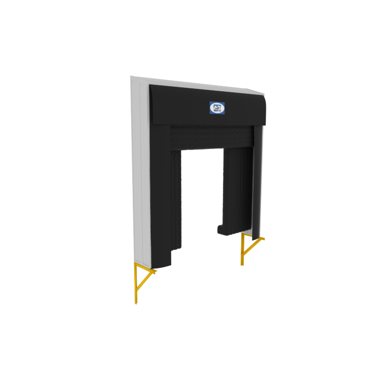
Inflatable Dock Shelter
An inflatable door seal is an accessory that achieves a sealing effect through inflation and expansion,primarily installed around the perimeter of doors (such as industrial doors,cold storage doors,loading dock doors,etc.). Definition & Core Function Inflatable Dock Shelter is a door accessory that achieves a sealing effect through air inflation. It is primarily installed around the perimeter of doors, such as industrial doors, cold storage doors, or dock leveler doors. Its core functions include: Sealing & Isolation: Fills the gaps between the door and door frame, preventing air leakage, dust ingress, noise transmission, and insect entry. Thermal Insulation & Energy Saving: Reduces heat or cold loss in cold storage or cleanroom environments, lowering energy consumption. Environmental Protection: Suitable for industrial or commercial environments requiring constant temperature, dust-free conditions, insect prevention, or odor control. Working Principle Inflation: Air is pumped into the internal air chambers of the dock seal using a built-in air pump, pneumatic system, or electric device, causing the seal to expand and press tightly against the door edges. Sealing State: Once inflated, the elastic materials (such as rubber or PVC-coated fabric) fill the gaps, forming an effective sealing barrier. Deflation & Retraction: When the door opens, the air chambers automatically deflate and retract to avoid obstructing passage. Specifications & Airtightness Dimensions WxH Top Extension Side Extension Blower Power Air Tightness Sealing Performance 3400x3400 1200mm 800mm 800mm 380v/220v 95% 3400x3600 1200mm 800mm 800mm 380v/220v 95% 3400x3800 1200mm 800mm 800mm 380v/220v 95% 3600x3800 1200mm 800mm 800mm 380v/220v 95% Note: Please inquire about customization for other sizes.
View Details -
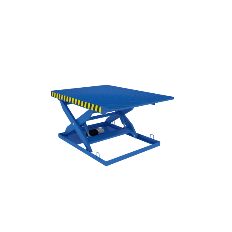
Heavy-duty Scissor Lift Platfor
Heavy-duty Scissor Lift Platform Structural Features Scissor Lift Platform is a type of equipment that achieves vertical lifting through a scissor-style mechanical structure. With its stable lifting performance and wide applicability, it plays an important role across multiple industries. Working Principle When the hydraulic system is activated, hydraulic oil in the cylinder pushes the piston rod to extend and retract, driving the scissor arms to expand around their hinge points, causing the platform to rise vertically. Conversely, when the hydraulic oil flows back, the scissor arms contract, and the platform descends. The change in the crossing angle of the scissor arms determines the lifting height of the platform. Thanks to its structural design, the platform remains level throughout the lifting process, ensuring excellent stability. Specification Parameters Model Loading Capacity Platform Dimensions Closed Height Travel Height Maximum Height HWPD201 2T 2000x2000mm 350mm 1200mm 1550mm HWPD202 2T 2000x2300mm 350mm 1300mm 1650mm HWPD203 2T 2000x2500mm 350mm 1600mm 1950mm HWPD204 2T 2000x3000mm 350mm 1600mm 1950mm HWPD401 4T 2000x2000mm 450mm 1200mm 1650mm HWPD402 4T 2000x2300mm 450mm 1300mm 1750mm HWPD403 4T 2000x2500mm 450mm 1600mm 2050mm HWPD404 4T 2000x3000mm 450mm 1600mm 2050mm HWPD601 6T 2000x2000mm 550mm 1200mm 1750mm HWPD602 6T 2000x2300mm 550mm 1300mm 1850mm HWPD603 6T 2000x2500mm 550mm 1600mm 2150mm HWPD604 6T 2000x3000mm 550mm 1600mm 2150mm Note: Lip Plate Options: Available in both manual and electric versions. Anti-Corrosion Process: Shot blasting + electrostatic powder coating + high-temperature baking finish. Customization: Multiple sizes and models available; non-standard dimensions can be tailored to your requirements. ▼ Common Colors: RAL 5005 RAL 7016 RAL 9017 Special color codes can be customized.
View Details -
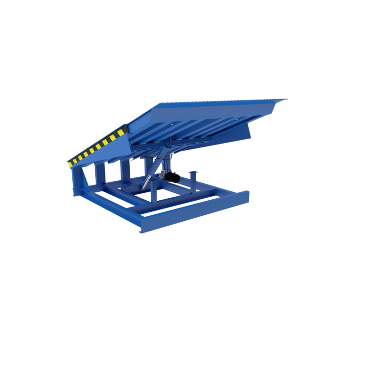
Telescopic Dock Leveler
Structural Features A Telescopic Dock Leveler is an adjustable platform designed to extend or retract its length through mechanical structures or hydraulic systems. It bridges gaps during cargo loading and unloading in logistics, warehousing, and industrial operations, temporarily expanding the working space. Its core function is to flexibly adapt to varying heights and dimensions of transport vehicles (such as trucks or containers), significantly improving cargo handling efficiency and safety. Key Advantages Improved Loading & Unloading Efficiency: Eliminates gaps or height differences between the platform and vehicles, allowing forklifts or hand carts to drive directly into the truck bed. High Adaptability: Retractable length adjusts automatically or manually based on vehicle type (box trucks, containers, etc.). Enhanced Safety: Equipped with anti-slip surfaces, cushioning devices, and guardrails to minimize cargo damage and workplace accidents. Space-Saving: Fully retracts into a fixed position when idle, preserving valuable dock floor space. Specification Parameters Equipment Size (W×L) Equipment Width (W) Equipment Length (L) Equipment Height (H) Foundation Pit Width (PW) Foundation Pit Length (PL) Foundation Pit Depth (PD) Extended Length W2000 × L2000 2000 mm 2000 mm 490–600 mm PW = W + 30 PL = L PD = H + 10 1000 mm W2000 × L2300 2000 mm 2300 mm 490–600 mm PW = W + 30 PL = L PD = H + 10 1000 mm W2000 × L2500 2000 mm 2500 mm 490–600 mm PW = W + 30 PL = L PD = H + 10 1000 / 1200 mm W2000 × L3000 2000 mm 3000 mm 490–600 mm PW = W + 30 PL = L PD = H + 10 1000 / 1200 mm W2000 × L3500 2000 mm 3500 mm 490–600 mm PW = W + 30 PL = L PD = H + 10 1000 / 1200 mm W2000 × L4000 2000 mm 4000 mm 490–600 mm PW = W + 30 PL = L PD = H + 10 1000 / 1200 mm W2000 × L5000 2000 mm 5000 mm 490–600 mm PW = W + 30 PL = L PD = H + 10 1000 / 1200 mm Note: Custom sizes are available upon request. Load Capacity & Technical Specifications Parameter Specification Details Dynamic Load 8 Ton Static Load 10 Ton Main Board Thickness 8 mm Panel Reinforcement Strips Rectangular tube: 80×120 mm / 100×150 mm Lip Plate Thickness 14 / 16 mm Base Frame 10# Channel steel Forklift Usage Scope Suitable for up to 3.5-ton forklifts Additional Technical Notes: Anti-Corrosion Finish: Shot blasting + electrostatic powder coating + high-temperature baking finish. Hydraulic Configurations: Single main hydraulic cylinder (X1) / Double main hydraulic cylinders (X2). Standard Colors: RAL 5005, RAL 7016, RAL 9017 (Custom color shades available upon request).
View Details -
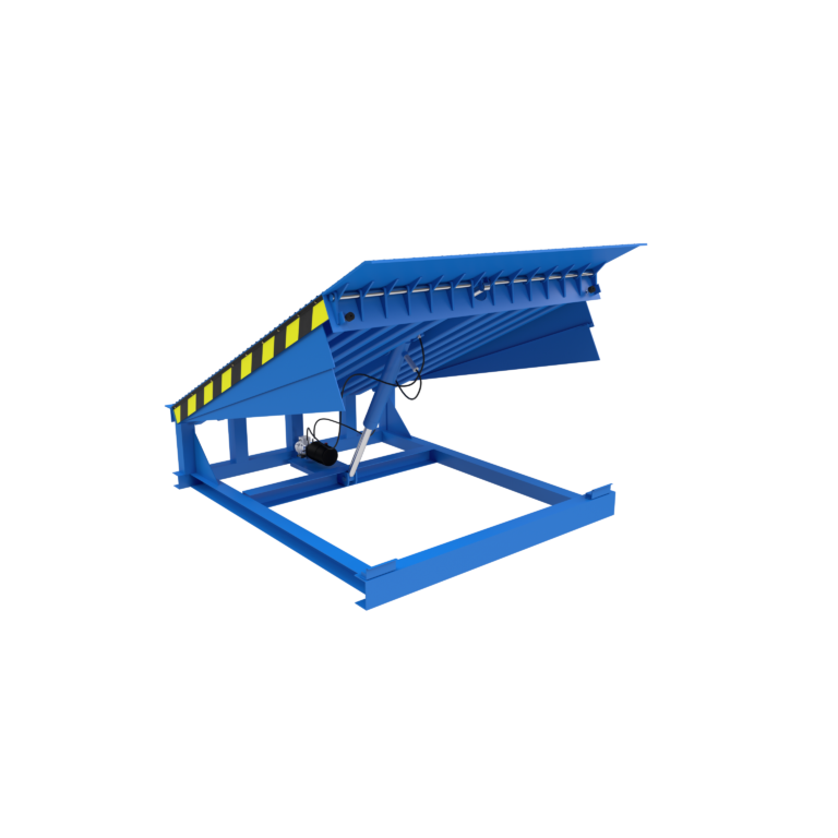
Hydraulic Dock Leveler
Structural Features Folding Dock Leveler is a kind of equipment with a unique structure and wide applications. Below is its related introduction: Composition: Usually consists of a main board and a flap board, with the flap board connected to the main board via hinges or similar methods. For example, the commonly used Folding Dock Leveler allows the flap board to rotate up and down to adjust the platform height. Material Selection: The main body is generally welded with high-strength steel to ensure sufficient strength and stability, capable of bearing heavy vehicles such as trucks and forklifts. The platform surface is usually equipped with anti-slip strips or steel plates to prevent cargo or personnel from slipping. Working Principle Taking a Folding Dock Leveler as an example, the platform tilt is achieved by a hydraulic cylinder. The tilt angle is usually adjustable between 7°–12°. After raising or lowering to the required position, the flap board is further adjusted via the hydraulic cylinder or electric push rod to align with the cargo truck or loading dock, forming a transitional slope that facilitates loading or unloading operations. Specification Parameters Equipment Size WxL Equipment Width W Equipment Length L Equipment Height H Foundation Pit Width PW Foundation Pit Length PL Foundation Pit Depth PD W2000xL2000 2000/1800mm 2000mm 490-600mm PW=W+30 PL=L PD=H+10 W2000x L2300 2000/1800mm 2300mm 490-600mm PW=W+30 PL=L PD=H+10 W2000xL2500 2000/1800mm 2500mm 490-600mm PW=W+30 PL=L PD=H+10 W2000xL3000 2000/1800mm 3000mm 490-600mm PW=W+30 PL=L PD=H+10 W2000xL3500 2000/1800mm 3500mm 490-600mm PW=W+30 PL=L PD=H+10 W2000xL4000 2000/1800mm 4000mm 490-600mm PW=W+30 PL=L PD=H+10 Note: Other sizes are available for inquiry and various specifications and models can be customized for your selection (including all types of non-standard custom sizes). Load Capacity and Type Selection Dynamic Load Main Board Thickness Panel Reinforcement Strips Lip Plate Thickness Base Frame Static Load Forklift Usage Scope 6T 6mm 4mm L/C-shaped steel 12mm 10# Channel steel 9T 2.5-ton forklift 8T 8mm 4mm L/C-shaped steel 14mm 10# Channel steel 12T 3.5-ton forklift 10T 8mm 14# I-beam 16mm 10# Channel steel 15T 4.5-ton forklift Note: Large-load capacity can be customized upon inquiry. Custom sizes, including non-standard dimensions, are available. “Dynamic load” refers to the load when the platform board is carrying cargo and the forklift is moving on the platform. “Static load” refers to the load when the platform is in a reset/closed state and the forklift is moving on the platform. Anti-Corrosion Process: Shot blasting + electrostatic powder coating + high-temperature baking finish. Optional Configurations: Single main hydraulic cylinder (X1) / Double main hydraulic cylinders (X2)
View Details -
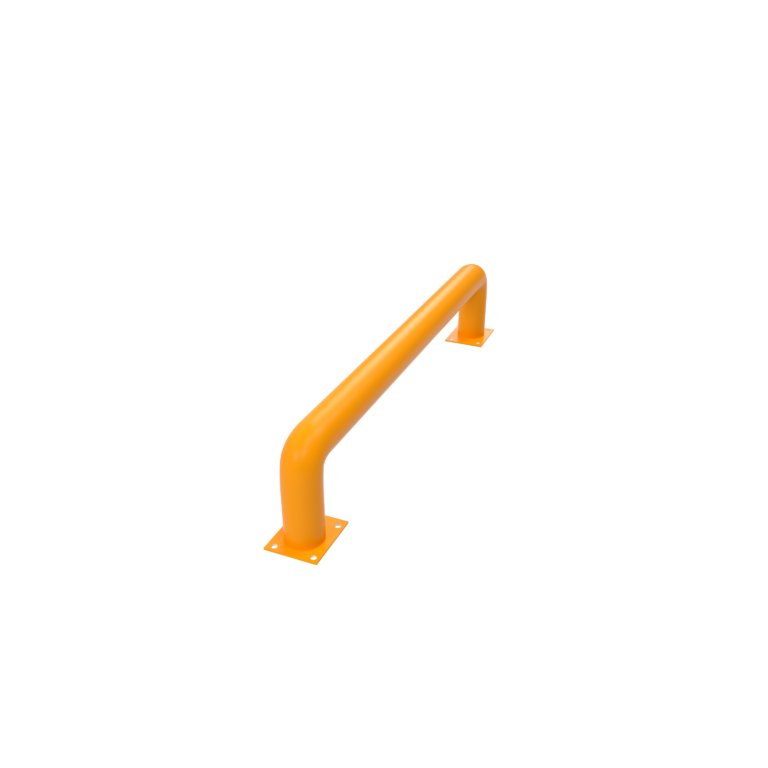
Heavy-Duty Steel Loading Dock Wheel Guides
Heavy-Duty Steel Loading Dock Wheel Guides | High-Visibility Safety Truck Alignment Guide Rails for Loading Bays 1. Product Overview Ensure seamless, safe, and precise truck docking with our Heavy-Duty Loading Dock Wheel Guides. Designed to assist truck drivers during reverse docking, these high-visibility steel guide rails automatically align incoming trailers with the loading bay, minimizing the risk of costly damage to dock shelters, building walls, and door seals. Featuring a unique flared/cranked entrance design, they smoothly "catch" and redirect truck tires into the correct path, making them an indispensable safety asset for busy logistics centers, warehouses, and industrial plants. 2. Key Features & Benefits Maximum Dock Protection: Prevents off-center trucks from colliding with expensive dock equipment, warehouse doors, and building infrastructure. Heavy-Duty Steel Construction: Manufactured from premium, thick-walled carbon steel pipes designed to withstand the immense impact and lateral pressure of fully loaded semi-trucks. Flared/Cranked Entry Design: The angled front section smoothly guides misaligned vehicle wheels into the straight lane without causing sudden tyre shock. High-Visibility Finish: Coated in safety yellow/orange powder finish (or hot-dip galvanized) to ensure maximum visibility for drivers, even in low-light, night, or harsh weather conditions. Secure & Easy Installation: Equipped with robust, pre-drilled baseplates for rock-solid surface mounting using concrete anchor bolts. 3. Product Specifications Parameter Specification / Options Product Name Loading Dock Wheel Guides / Truck Alignment Rails Material Heavy-duty Carbon Steel / Low Carbon Steel Surface Treatment Outdoor Powder Coating (Safety Yellow/Orange) / Hot-dip Galvanized Tube Diameter $\varnothing 140\text{mm}$ (5.5") / $\varnothing 165\text{mm}$ (6.5") (Customizable) Wall Thickness $4.0\text{mm}$ / $4.5\text{mm}$ / $5.0\text{mm}$ / $6.0\text{mm}$ Overall Length $2000\text{mm}$ / $2400\text{mm}$ / $3000\text{mm}$ (Customizable) Mounting Type Surface-mounted with Baseplates (Bolt-down) / Cast-in (Concrete-embedded) Application Loading docks, logistics parks, warehouses, distribution centers 4. How It Works & Installation How It Works: As a truck backs into the loading bay, the wide flared opening of the wheel guides catches the rear wheels. If the truck is misaligned, the rail gently nudges the tires, forcing the vehicle to straighten out and line up perfectly centered with the dock bumper and shelter. Installation Options: Surface Mounted (As shown in image 导向柱.jpg): Position the rails on the concrete slab, drill holes through the heavy-duty baseplates, and secure them tightly using mechanical or chemical anchor bolts. Deep Embedded (Optional): Extended pipe legs are cast directly into fresh concrete for ultimate impact resistance. 5. Ideal Applications Logistics & Distribution Centers with high-frequency truck turnarounds. Cold Storage Warehouses requiring perfect sealing to maintain temperature control. Manufacturing Plants with dedicated material handling and loading bays. Automated Warehouses where AGVs or autonomous trucks require high-precision docking.
View Details